Laser TEC and Current Driver Mount

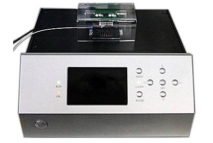
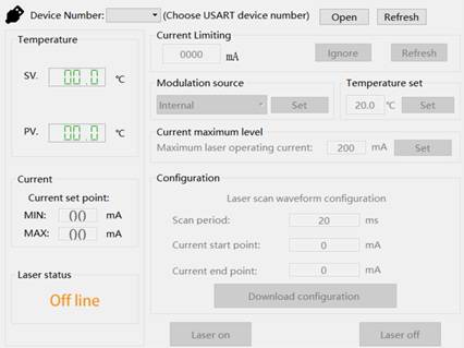
Precise control of the temperature and current for the DFB laser is required in order to achieve high-precision spectrum applications. KONGTUM developed a high-performance laser controller integrated TEC driver, low-noise current driver and a 14pin Butterfly Laser mount. For other packaging like TO-can, KONGTUM also has TO laser mount. The Driver Mount also has a USB com port, can be monitored and controled through the PC software.
Features:
Compact all-in-one laser diode controller
CW operation and external modulation up to 5MHz
Operating current range 15 to 2000mA
USB port and control software included
Graphical User Interface for real-time monitoring, control and data logging
14-pin butterfly mount or 14-pin DIL mount included
Additional mounts are optional
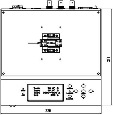
Compact size (164x105x95mm)
110-240V AC adapter included
Parameters
PC Software GUI
Dimensions (mm)
Modulation Signal Limitations
Parameters | Values |
Laser Mount Type | 14pin Butterfly Package/DILPacakge |
Pin Definition | S-Type/P-Type (Customizable) |
Power Supply | 220VAC 50Hz |
Power Consumption | Max 18W |
Current Driver | |
Max Driving Current | 0~500mA/0-2000mA (Optional) |
Max Output Voltage | 5V |
Internal Ramp Time | 10~200ms (Set by PC Software) |
Internal Ramp Current | 0~500mA (Set by PC Software) |
External Modulation Bandwidth (-3dB) | DC~100kHz (Customizable) |
External Modulation Coefficient | 100mA/V |
External Modulation Voltage Range* | 0~5V DC |
External Modulation Input Port | BNC, Female |
External Modulation Input Impedance | 5kΩ |
Temperature Control | |
Temperature Control Range | 5~50℃ |
Stability (24hr constant ambient temperature) | <0.01℃ |
Temperature Sensor | NTC Thermistor, 10kΩ±1% @ 25℃ |
TEC Peak Current | 1A |
TEC Peak Voltage | 5V |
Control Port | DB9, Male |
Others | |
Computer Port | USB type B |
Operation Temperature | 0~50℃ |
Store Temperature | -10~80℃ |
Dimension (LxWxH) | 21.1cm*22.0cm*10.1cm |
Weight | 700g |
Note: * The modulation signal voltage range is determined by the operating current of the laser diode. The LASER DIODE may be permanently damaged if the current is modulated over the Max Operating Current. Before the modulated signal was inputted, please make sure the signal peak voltage is below the laser diode Max Operating Current.


1. Internal modulation signal
When using the internal modulation signal, please refer to laser parameters, set the appropriate current maximum value on the PC software to limit the modulation current in a safe range.
2. External modulation signal input
When using the external modulation signal input, should refer to the maximum allowable operating current Imax of the laser. The peak value of the modulation signal voltage should be below Imax/(0.1A/V). For example, the maximum operating current of the laser is Imax=0.15A, then the peak modulation signal should be less than 0.15/0.1=1.5V. The current limit value is also setted on the PC software.
