
CRDS Cavity
Cavity Ring Down Spectroscopy (CRDS) is a new type of spectral detection method emerging in recent years. CRDS has a long absorption optical path and is not affected by the fluctuation of light source intensity. It is especially suitable for detecting weak absorption, and easy to quantitatively measure. It is used for trace gas detection and accurate measurement of lens reflectance and so on.
KONGTUM offers complete sample-cell assemblies for customers interested in CRD measurements of flowing and static gases, and also all components of the CRDS system. Please refer to other webpages.
Features:
High sensitivity, effective absorption optical path of several to tens of kilometers;
Not affected by fluctuations in light intensity, measure ring-down velocity rather than intensity;
The wide applicable spectral range, generally ±5% of the center wavelength;
The fast detection speed, a ring-down can be completed in milliseconds.
Parameters
Dimensions (mm)
Adjustment Advices
Parameters | Values |
Effective Optical Path | Hundreds meters to kilometers (customizable) |
Wavelength Range | 0.2 ~ 12um (customizable) |
Laser Type | Puls or CW |
Laser Power | >10mW |
Cavity Volume | 245mL (customizable) |
| Cavity Length | 500mm (customizable) |
| Mirror Reflectivity | >99.9%@central wavelength (customizable) |
| Mirror Adjustment | Manual / PZT driven |
| Working Temperature | 20~50℃ |
| Working Pressure | 10Pa ~ 200KPa |
| Cavity Material | SUS304 with Teflon Coating (customizable) |
| Inlet and Outlet | Needle Valve with φ6mm Ferrule (customizable) |

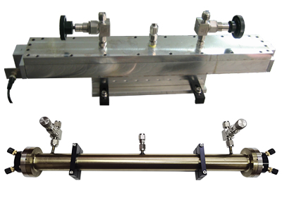
Top View of The 500mm Cavity

End View of The 500mm Cavity
In order to achieve ring-down and an effective optical path, users need to adjust the entire optical path of the cavity, mirrors and the laser to the best position. The optical adjustment is a complicated, delicate and time-consuming work, which requires users to be patient and orderly.
Followings are some advices for reference:
1. Before installing mirrors, initially adjust the relative position between the cavity and the incidence beem, so that the incidence beem and the cavity are initially coaxial;
2. Install the mirror at the output end first, and adjust it with the incidence beam, so that the incidence beam, the output end mirror and the cavity are coaxial. The alignment screws can be locked after adjustment;
3. Install the mirror at the input end and adjust it with the incidence beam, so that the incidence beam, the input end mirror and the cavity are coaxial;
4. In order to facilitate adjustment, it is recommended to use single-mode red laser with better beam quality. After the final adjustment is completed, it will be observed that all the light spots coincide to one point and form interference fringes.